Types of forces
A force is a push or pull acting upon an object as a result of its interaction with another object.
Contact forces
The contact force is a force between the contacting surfaces of two bodies.
- Applied force - a force that is applied to an object by a person or another object
- Normal force - contact force perpendicular to surface of an object that is in contact with another stable object.
- Frictional forces: kinetic and static friction. It is the component of the contact force tangent to the surface as an object moves across it (kinetic) or makes an effort to move but does not move across it (static).

- Air and liquid resistance; drag force. The air resistance is a special type of frictional force that acts upon objects as they travel through the air. The liquid resistance force is a force acting opposite to the relative motion of any object moving with respect to a surrounding fluid.

Here, þ - liquid or air density; v – speed of the moving object; A – frontal area of the object moving through the liquid or gas; C d – coefficient of drag; V – velocity unit vector.
- Tension and compression. The tension force is the force that is transmitted through a string, rope, cable, or wire when it is pulled tight by forces acting from opposite ends. Compression force is the application of power, pressure, or exertion against an object that causes it to become squeezed, squashed, or compacted.
- Spring (elastic) force (Hooke’s Law) - a force exerted by a compressed or stretched spring upon any object that is attached to it.

Here, k – spring constant; x – spring stretch or compression.
Non-contact (action-at-a-distance) forces
- Gravity force (also known as Weight) - a force with which the earth, moon, or other massively large object attract another object towards itself.
- Electric force - a repulsive or attractive interaction between any two charged bodies.
- Magnetic force - an attraction or repulsion force that arises between electrically charged particles because of their motion
Newton’s Laws of Motion
Newton’s First Law
An object remains at rest (if originally at rest) or moves in a straight line with constant velocity if the net force on it is zero.
![]()
Newton’s Second Law
Newton stated that the acceleration of an object is directly proportional to the net force acting on it and in the direction of that net force, and inversely proportional to its mass.

Newton’s Third Law
The forces of action and reaction between interacting bodies are equal in magnitude and opposite in direction.
![]()
Newton's Universal Law of Gravitation
One additional law attributed to Newton concerns mutual attractive forces between two bodies. For any two masses, the force is directly proportional to the product of the two masses and is inversely proportional to the square of the distance between them.
![]()
where g is a gravitational constant for the two interacting masses.
Free Body Diagram
In physics and engineering, a free body diagram is a graphical illustration used to visualize the applied forces, moments, and resulting reactions on a body.

Free-body diagrams allow to analyze an object in isolation without distractions.
Force equilibrium
A force is a vector, with both a magnitude and a direction associated with it. If the size and direction of all forces acting on an object are balanced, then there is no net force acting on the latter. In this case the object is in equilibrium.

The use of the force equilibrium principle in engineering design is illustrated on the NASA web site in the example of the three-force equilibrium and its application to the Space Shuttle descending behavior analysis.

Laws of Thermodynamics
Thermodynamics is the study of the effects of work, heat, and energy of a system and it is only related to the macroscopic (large-scale) changes and observations. It is not considered at the atomic or molecular level.
First law of thermodynamics
The first law of thermodynamics is an extension of the law of conservation of energy and it states that energy can be transformed (i.e. changed from one form to another) but cannot be created or destroyed.
It defines the change in internal energy of a system between two equilibrium states as being equal to the difference of the heat added to the system and the work done by the system
E=Q-W
Second law of thermodynamics
For the second law of thermodynamics, the main conceptual term is entropy. Entropy is the measure of a system's thermal energy per unit temperature that is unavailable for doing useful work.
The second law of thermodynamics states that the total entropy of an isolated system can never decrease over time (the system cannot be more “organized” without external input) and is constant if and only if all processes are reversible. A reversible process is one which can change state and then return to the original state.
Third law of thermodynamics
The third law of thermodynamics states, that the absolute zero-temperature 0 K cannot be reached by a finite number of steps, i.e., no system can reach absolute zero.
Thus, the third law of thermodynamics can be formulated as the entropy of a system cannot increase infinitely and it approaches a constant value as the temperature approaches absolute zero, where the atoms will stop moving.
Maxwell's Reciprocal Theorem
Maxwell's reciprocal theorem states that in a linearly elastic structure, the deflection at any point A due to a load applied at some other point B will be equal to the deflection at B when the same load is applied at A.

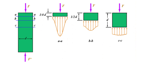
Saint-Venant’s Principle
The principle states that as the distance from the point of load application becomes greater, the local effects are reduced such that they can be considered not to be present.
In design practice, this principle calls for the requirement that supporting bearings should be spaced 3-5 shaft diameters apart for the effective resistance to the moments applied to the shaft.
Abbe Principle
The Abbe Principle (Abbe errors) was formulated: Small angular deflections are amplified by distance and create large linear displacements, meaning that angular errors cause increasing translational errors as one moves further from the source.

Golden Rectangle
The Golden Rectangle is a concept formulated by the ancient Greek philosopher Pythagoras and describing a rectangle whose sides are in proportion, such that when a square is cut from the rectangle, the remaining rectangle has the same proportions as the original one. Mathematically, this can be expressed as:

where a is the length of the bigger side of the rectangle, and b is the length of its shorter side. Assigning b=1, from this equation one can readily find a=1.6180339

Thus, a Golden Rectangle concept introduces the Golden Ratio that is approximately equal to 1:1.62.
Parallel Axis Theorem
A practical approach in mechanical engineering to the analysis of the complex parts is to calculate moments of inertia by breaking down a complex shape into simple parts, looking up the moments of inertia for these parts separately, bringing the obtained moments of inertia to common reference (axis of rotation), and adding them together to find the overall moment of inertia.
To bring these moments of inertia to the common axis of rotation, the Parallel Axis Theorem is used. With it the moments of inertia can be adjusted so that they are all taken about same standard point.

Mass moment of inertia:
IO = IC + md ^2 ,
where m – mass of body.
Area moment of inertia:
IO = IC + Ad ^2 ,
where A – area of the cross-section.
Strength and other load-related characteristics
Strength is an inherent property of a part material affecting reciprocity between a particular material and process. The more load a material can bear, the more strength it has.
There are four main types of strength based on loading types:
- Compressive strength – maximum compressive load a body can bear prior to failure, divided by its cross-sectional area;
- Shear strength – maximum shear load a body can withstand before failure occurs divided by its cross-sectional area;
- Tensile strength – maximum tensile load a body can withstand before failure divided by its cross-sectional area. This property is also sometimes referred to Ultimate Tensile Stress or UTS;
- Torsional (twist) strength – maximum amount of torsional stress a body can withstand before it fails, divided by its cross-sectional area.
In regard to deformation before fracture, the three types of strength are:
- Elastic limit – maximum stress to which a specimen may be subjected and still return to its original length upon release of the load;
- Ultimate strength – maximum stress that a solid material can withstand before its failure;
- Yield strength – the stress at which a material changes from elastic deformation to plastic deformation.
Static or Dynamic Load?
All machine elements are subjected to different types of loads that act due to energy, torque or power transmission, their own weight, frictional resistance, inertia or centrifugal forces, or temperature gradient. Loads can static or dynamic.
- Static load (a stationary force or moment acting on a machine element) does not change in magnitude, point of application or direction, e.g. dead weight of machine elements.
- Dynamic load changes in magnitude or direction, or both, with respect to time, e.g. load transmitted to the pedal of a riding bike from the foot of a cyclist.
Stress and Stress Concentration
The term stress is used to express the loading in terms of force applied to a certain cross-sectional area of an object:
σ=F/A,
where F is the tension or compression force acting perpendicular to an imaginary plane surface passing through a piece of material and A is the cross-section area. Stress distribution may be uniform or non-uniform, depending on the nature of the loading condition.
During design process there are few aspects related to stress that should be addressed:
- Avoid bending stresses. Tension and compression are preferable.
- Triangulate for stiffness. Triangulation applies to structures and structural elements.
- Avoid elements in the design causing stress concentration.
Strain
To characterize the deformation of a material in response to stress, another property called strain (ε) is defined as the fraction of elongation (increment of length) or contraction (decrement of length) in a material caused by a stress:
ε=∆L/L
An elastic material has a linear relationship between stress and strain:
σ=εE,
where E is called the elastic, or Young’s, modulus, i.e. the slope of the stress/strain diagram in the elastic region.
The strength of a material is generally defined as the maximum stress it can withstand without breaking.
Hooke’s Law
Hooke’s law states that within the limit of proportionality, the extension of a material is proportional to the applied force, or the force applied to a material is proportional to the elongation of the material:
F=kx
From this follows another formulation: Within the limit of proportionality of a material, the strain produced is directly proportional to the stress producing it. Most engineering structures are designed to undergo relatively small deformations, involving only the straight-line portion of a corresponding stress-strain diagram. Thus, the stress σ is directly proportional to the strain ε for that initial portion of the diagram:
σ=Eε
The equation corresponds to normal stress and normal strain. Here the constant of proportionality between strain and stress is called Young’s modulus of elasticity and is denoted by the symbol E.
The largest value of the stress for which Hooke's law can be used for a given material is known as the proportional limit of that material.
Factor of Safety Method
Factor of safety (FoS) design method is the method of design that employs the concept referring to one of two things:
- the actual load-carrying capacity of a structure or component, or
- the required margin of safety for a structure or component according to code, law, or design requirements.
In this method, the maximum stress or stresses produced in a part by the actual load are kept below the minimum possible strength by a suitable design factor or margin of safety, to ensure that the part will not fail.
Vibrations
(Daniel J. Inman, 2014, Engineering Vibration, Pearson Education, Upper Saddle River, New Jersey)
One very important task in design is to create structures and machines such that they vibrate as little as possible. Engineers often start to solve this problem after a product is designed, prototyped, and tested, because in many cases vibration problems are found late in the process. Thus, the product must be redesigned according to specific criteria.
Potential difficulties in design for vibrations
- One important problem might be in appropriate equivalence of the simple single-degree-of-freedom spring–mass model to the dynamics of the part. It may happen that a more sophisticated multiple-degree-of-freedom model is more adequate for this purpose.
- Another possible problem with a developed design is that the stiffness of the part may not be allowed to be lower than a certain value because of load requirements (static deflection) or other design constraints. A solution here may be the change of the mass, but it may have its own constraints.
As a result, in some cases, it may not be possible to design a system with the desired vibration response. In other words, not all design problems have a solution.
An important consideration in specifying vibration response is to specify the nature of the input or driving force that causes the response. Disturbances, or inputs, are normally classified as either shock or as vibration, depending on how long the input lasts. An input is a shock if the disturbance is a sharp, aperiodic one lasting a relatively short time. In contrast, an input is a vibration if it lasts for a long time and has some oscillatory features.
The distinction between shock and vibration may not be always clear as the sources of shock and vibration disturbances are numerous and very difficult to place into categories. Often, inputs are a combination of several sources of different categories.
Friction
The first two classical laws of friction, usually attributed to a French physicist Guillaume Amontons (1663-1705), read:
- The force of friction is directly proportional to the applied load;
- The force of friction is independent of the apparent area of contact.
However, in modern field mechanical design it is known that:
- Friction force is NOT proportional to load, NOT independent of area, and NOT independent of speed;
- Friction coefficients from tables represent specific conditions. Parameters of a particular application may be different.
- High friction and high wear do not always equate.
To manage friction, engineers and designers can use different approaches, some of them are:
- Making friction forces insignificant compared to other forces;
- Always preferring rotary over linear motion;
- Using rolling element bearings for drastically lower friction with high loads;
- Avoiding sliding contact of similar materials; etc.
Design for Reliability Method
Design for reliability is a collection of techniques that are used to modify the initial design of a system to improve its reliability (National Research Council, 2015. Reliability Growth: Enhancing Defense System Reliability. Washington, DC).
The statistical measure of the probability that a mechanical element will not fail in use is called the reliability of that element. It can be quantified as:
0 ≤ R ≤ 1
If in the above equation R=0.90 that means that there is 90% chance that the part will perform its proper function without failure.
Analysis that leads to an assessment of reliability addresses uncertainties, or their estimates, in parameters that describe the situation.