Lathe (WEILY TY-1340GH)
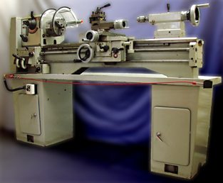
Emergency Stop
The emergency stop (E-stop) system consists of the following components:
- E-Stop switch
- Pull-cord (running along the length of the chip tray
- Plunger latch pin
- RESET button
Description
Power to the lathe is applied through a relay that is activated via the RESET button. The Forward/Reverse switch controls the direction of motor rotation. If the lathe is running and the power is interrupted, say by a power failure, the lathe will remain off until the RESET button is pushed.
The E-stop switch is a 3-position switch. Under normal operating conditions the switch plunger must be situated in the central position, as extreme positions signal a problem and causes the lathe to shutdown. Tension from the pull-cord keeps the plunger in the proper position during normal machine use.
Pulling the pull-cord pulls out the E-stop plunger and activates the emergency stop system. The plunger latch pin prevents the plunger from returning to the central (operating) position after the cord is released.
To recover from an emergency stop
- Set the Forward/Reverse switch to STOP
- Pull the plunger latch pin
- Press the RESET button
Preparing to Run the Machine
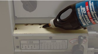
Oil the Quick-Change Gear Box
The gears in the quick-change box are not automatically oiled during machine operation. Hence, the gears need to be manually lubricated prior to using the lathe for the day.
Remove the cover above the quick-change gear box.
Apply a few drops of thick oil (e.g., 85W-140 gear oil) into each of the six (6) oiling holes, then replace the cover.
Setup Power
Ensure that Forward/Reverse switch is in the STOP position.
Pull the E-stop cord and confirm that the chuck cannot be turned by hand.
Pull the plunger latch pin on the E-stop switch to reset the switch.
Press the RESET button to activate the relay that applies power to the lathe and release the motor brake.
Use the Forward/Reverse knob as usual.
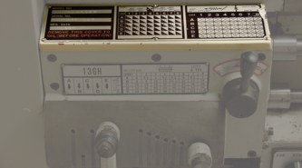
Motor Brake
KIT: #BRK-10 208-230/460
CAT #A1303
Model: 620010-5605-51Z
Manuals
The brake action is controlled by a lever shown in the photo to the left. The lever may be placed in one of two positions, despite the appearance to the contrary.
RESET: This is the normal lever position. During an emergency stop the brake will act to stop the motor.
RELEASE: (90-deg rotation from the RESET position.) In this position the brake is disengaged and cannot act.
Lathe Guard Shield
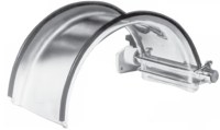
The lathe has been fitted with a Flexbar Lexan Latheguard™ ![]() , Model No. 13060. According to the manufacturer:
, Model No. 13060. According to the manufacturer:
“All Flexbar™ Latheguards are manufactured using 3/16" thick polycarbonate material for the shield portion of the guard. Although polycarbonate is one of the strongest and most impact resistant materials available, several of today’s more “aggressive” coolant mixtures splashing on the polycarbonate shields can cause discoloration, crazing or cracking. These include coolants containing one or more of the following:
Trichloroethylene
1-1-1 Trichlorethane
Amines
or solvents in the above chemical families.It is recommended that an alternative coolant be used to prevent the above situation from occurring. In any case, at first sign of crazing or cracking the Latheguard™ shield must be replaced with a replacement shield as a safety precaution. Please refer to the Flexbar
catalog for replacement shield order numbers.”
Warning
Applying too much torque to the acorn nuts used to hold the Lexan shield to the mounting bracket may result in cracking the shield. DO NOT OVERTIGHTEN.
Gearbox
Oil Capacity
The headstock takes ~0.6 gallons (2.2L) of Shell Tellus 32 hydraulic oil. Fill the headstock so that the oil level is at 3/4 of the oil sight.
Gasket Template
This is a photocopy of the original gasket ![]() on the gearbox. Print it full-size on ledger sized paper.
on the gearbox. Print it full-size on ledger sized paper.